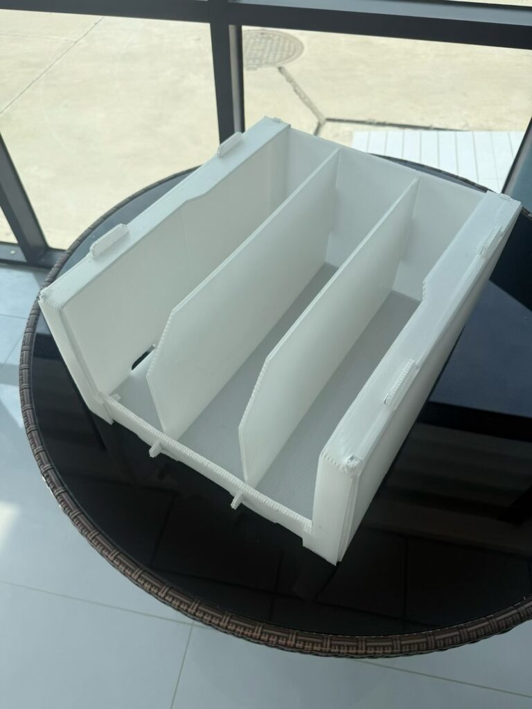
A divider can match the part drawing and still be wrong for the tote. I usually see the problem when the design has been reduced to one cell-size calculation. The number is correct, but the operating conditions were never included.
First, nominal dimensions are not the same as the working range. Part tolerance, divider-slot tolerance and the usable internal size of the box all contribute. A cell that looks generous on screen may become tight after conversion and assembly.
Second, loading direction changes the required clearance. An operator lowering a part vertically needs different access from someone sliding it sideways. Handles, flanges and fragile surfaces can also make the theoretical path impossible.
Third, the outer container matters. Walls can taper or flex. Corners, seams and closures reduce usable space. A divider that fits a flat internal rectangle may interfere once it is placed in the actual box.
Fourth, transport is dynamic. Clearance that helps loading can also allow movement. The design has to balance access with control at the contact points that the component can tolerate.
My preferred review sequence is simple: confirm the part and safe contact areas; measure the usable box; record loading and removal; assemble a representative sample; then document the accepted structure. The drawing remains important, but it becomes one piece of evidence instead of the whole decision.
Next step: submit the application details for a project-specific review.